Design time was probably the most complex. There was a lot of existing elements that had to be included. As already mentioned in previous post I have tried different approaches but finally ended up with recreating 1208 3 Axis Mini Assembled CNC. I do not plan to show first drafts but rather focus on final solution. Please find downloadable project at the end of this post.
Parts list
Here is the list of items that were used in design:
- T8 Lead Screw Rod (2mm pitch, 200mm length) - x2
- T8 Anti Backlash Nut (2mm pitch) - x2
- T8 Lead Screw Rod (2mm pitch, 100mm length) - x1
- T8 Brass Nut (2mm pitch) - x1
- Linear Shaft 8mm (200mm length) - x4
- Linear Shaft 8mm (80mm length) - x2
- Shaft Coupler D14L25 (5x8 inner diameter) - x2
- Linear Bearing LM8UU - x10
- 608ZZ Bearing - x2
- Plywood (90x150x8mm) - x1
- Nema17 Stepper Mottor (17HS4401) - x3
- 775 DC Motor (12V) - x1
- ER11A with collet (5mm diameter) - x1
- Power supply (T-120W-12V) - x1
- Anet A8 Main Board - x1
- Screws and nuts
- Wires and connectors
I have used some models found on internet and mostly downloaded from GrabCAD or McMaster-Carr Component.
Frame
My first idea was to keep it simple by following closesly 1208 design. So I have started with defining the main frame in the same way. The only change was in the size which was constrained by build volume that my 3D printer was able to handle.
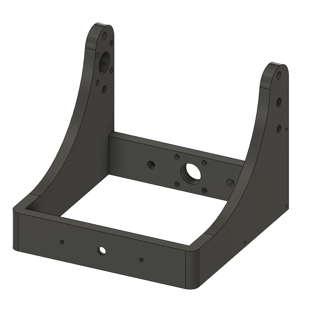 First approach to main frame design
Unfortunately while slicing it for the first time I have found out that print time will be around 15h+ for really low quality settings. Nevertheless I have attempted to print. Results were unsatisfying as expected though.
I have decided to split frame into easily printable parts.
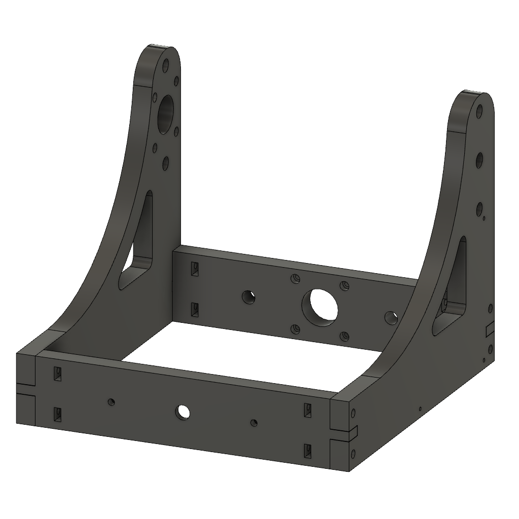 Frame sliced into 4 pieces
As you can see the parts were splited in a way that made it easy to assemble afterwards. I knew what margins to use for frame joints based on expierience gained from previous designs. Everything fitted very well on first try. Each part has taken around 8-11h to print with reasonable quality.
Frame adaptation was probably the biggest change in the design that I have made.
Bed
I have decided to use plywood as a material for bed. It should be good enough to mount PCB on top of it. Additionaly it should be fairly cheap and simple to replace it when needed.
Housings for LM8UU bearings and mount for lead screw were designed for 3D printing.
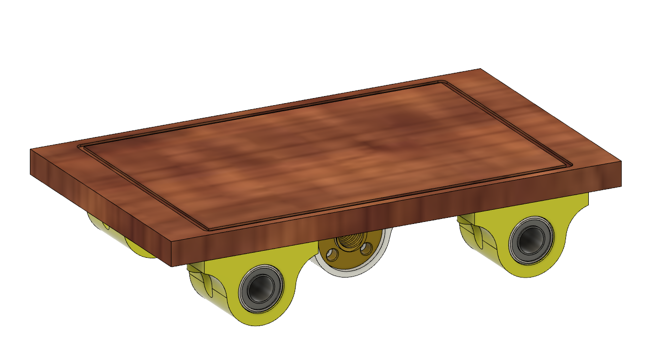 Plywood bed assembly
X carriage
In comparison to 1208 design I have decided to allow for smaller Z movement. This means that the carriage is smaller. Z rods are secured in bottom part. Stepper motor is raised with spacers to minimize influence of shaft coupler on Z movement range. Height of part which holds spindle motor is also smaller for the same reason.
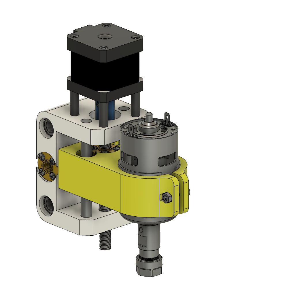 X Carriage assembly
Details
There are couple smaller decisions that had to be made.
X Stepper spacer
To ensure full range of movement on X axis I had to add spacer between X stepper motor and frame. This spacer was designed as full body instead of single spacers as it was for Z axis.
Electronics mount
Power supply and motherboard taken from Anet A8 printer has been attached to sides of frame with small spacers.
Rubber feets
To minimize vibrations and ensure good grip to the ground I have designed feets. They will be printed in flex filament. I have used holes in frame which initially were designed for keeping nuts.
Final model
Below is the render for final version of the design.
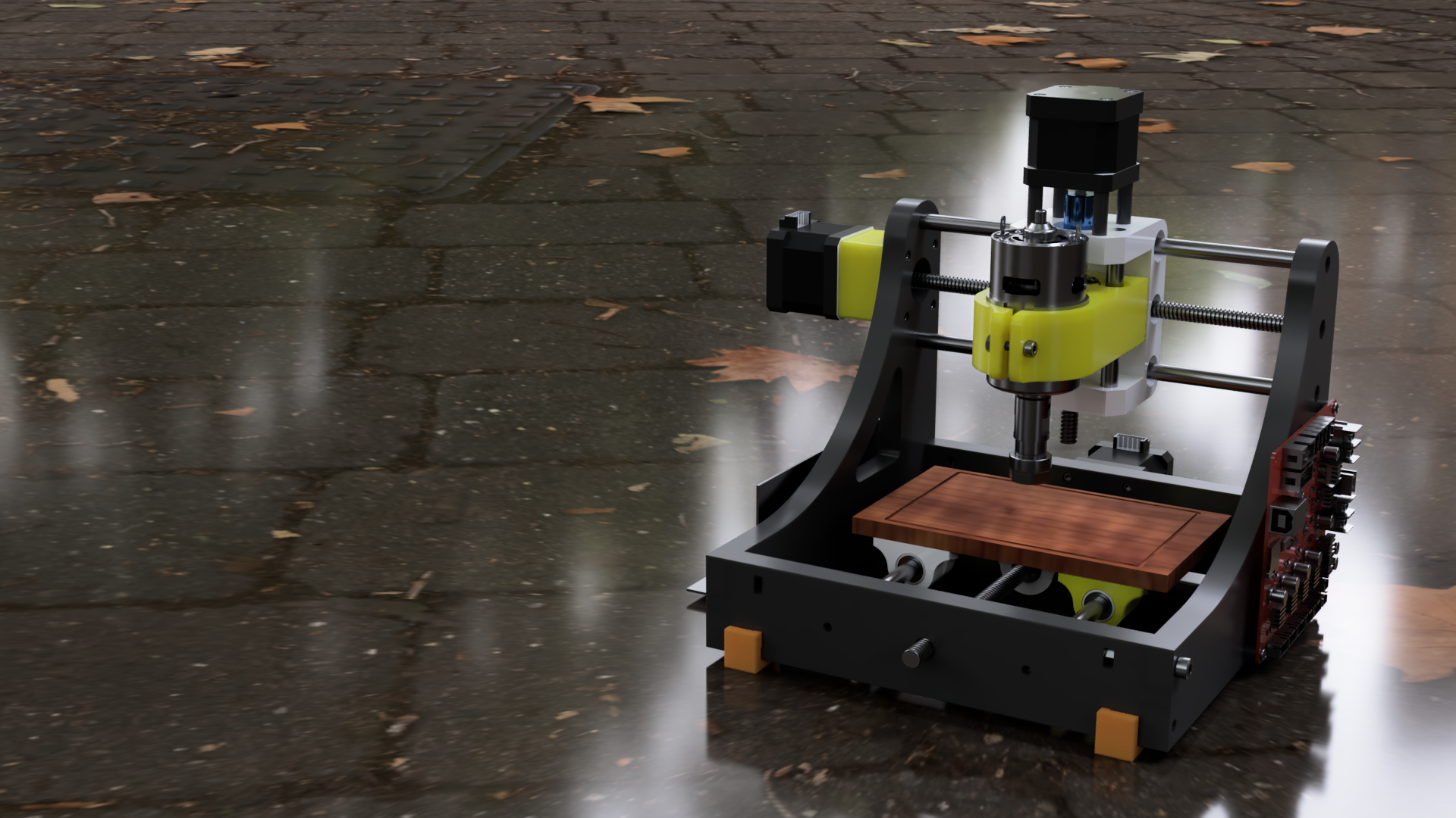 Rendered model of CNC for PCB
Here you can download project in Fusion 360.