Putting into effect the design took significant amount of time. It was filled with waiting for prints to finish and applying fixes when there were issues. Second part of course was waiting for all bought items to arrive. Let’s take a look what I had to struggle with.
Frame
I have started with the biggest part to print. Well… at least in the first design frame was a single part. It was the first time I was about to use the full size of build plate of my 3D printer. If you haven’t seen it before you might check previous post about design changes here.
Fixing the 3D printer first
This part probably should get a separate post (and hopefully it will in future!) but for now I would like to share some adjustements that I had to do before printing the frame. My 3D printer is modified Anet A8. One of mods I have made is replacement of original frame from acrylic to one based on aluminium profiles. I have also added proximity sensor. For some reason it was always leveling incorrectly on one side of the heated bed. After some struggling I have found the reason. It was uneven frame.
Printing single-piece frame
As already mentioned I have tried to print the single-pieced frame. I had some time constraints which I could not violate. I have reduced quality to make it possible for print to last around 15h. Unfortunately print was not strengthful enough. Main issue of the print was underextrusion caused by the fact that extruder was not able to give enough filament. Maybe it would be good enough to reprint with higher nozzle temperature but I just decided to change the approach.
Printing splitted frame
The main issue with this approach was that side parts where still pretty big and were using almost entire heated bed. The only difference is that this time much more filament was placed on build plate. Thankfully steps undertaken in before helped with easy printing of splitted frame.
Printing with fine quality took around 6-8 hours per part. I have printed all of them using black PLA Prusament with 0.4mm nozzle and 0.2 layer height. I was suprised how firm those parts came out.
I have screwed all parts together using some M5 screws. Threads in holes were done by screws themselves. Pockets that were initially put there for nuts were actually not needed.
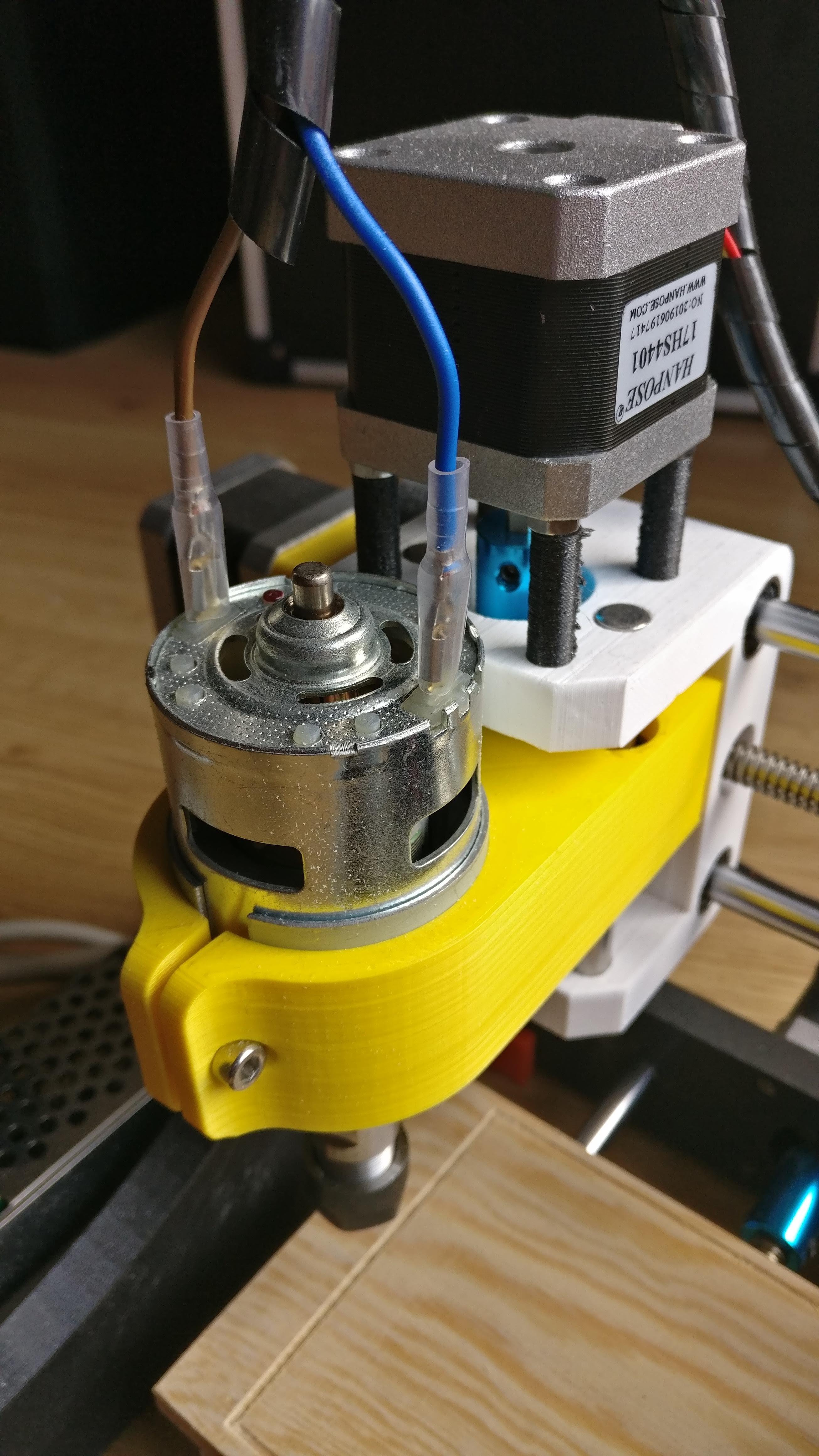
I have installed 608ZZ bearings for lead screws and mounted stepper motors.
Build plate
Build plate required couple parts:
- 4x LM8UU bearing housings
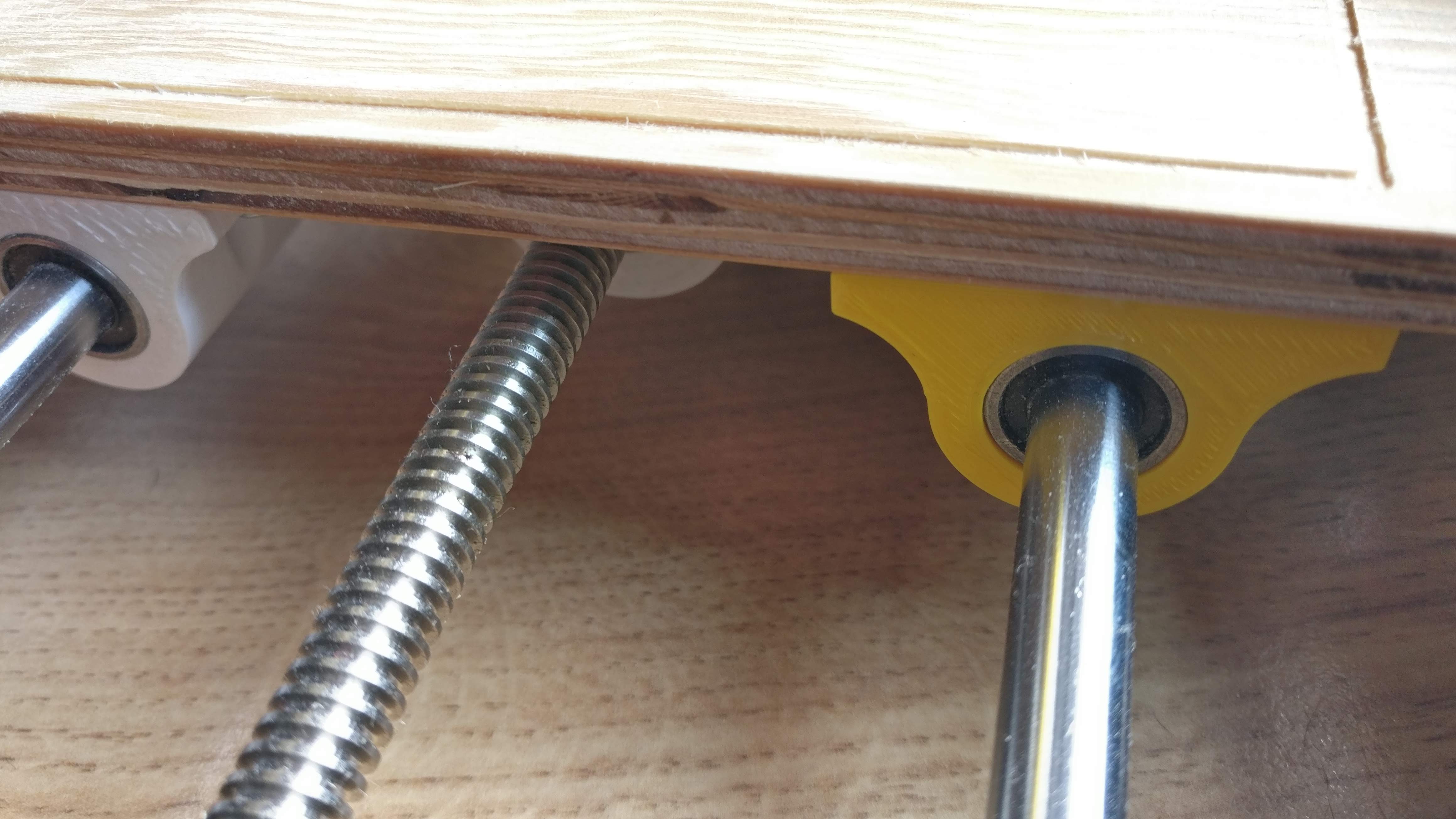
- mount for lead screw nut
Housings were good place to test print margins for mounting LM8UU bearings. After some trial an errors I have found correct value which fitted for my nozzle and filament.
Mount for lead screw nut had to be redesigned. Firstly it was simplified as much as it was possible. Unfortunately I have found out that it was hard to screw nut straight. In second approach I have actually added some additional material just to keep it well positioned.
X Carriage
I have decided to mount LM8UU bearings directly in X Carriage part. The main problem here was to correctly define printing margins for inner diameter of holes which were supposed to keep bearings inside. Instead of doing some simple print just to check those I have actually tried printing the whole part. I do not need to say that it was mistake. I had to reprint the whole carriage just to fix incorrect margins. As a test print to define those margins correctly I have used LM8UU bearing housings (check Build plate).
Putting everything together
You can check below photo for final result.
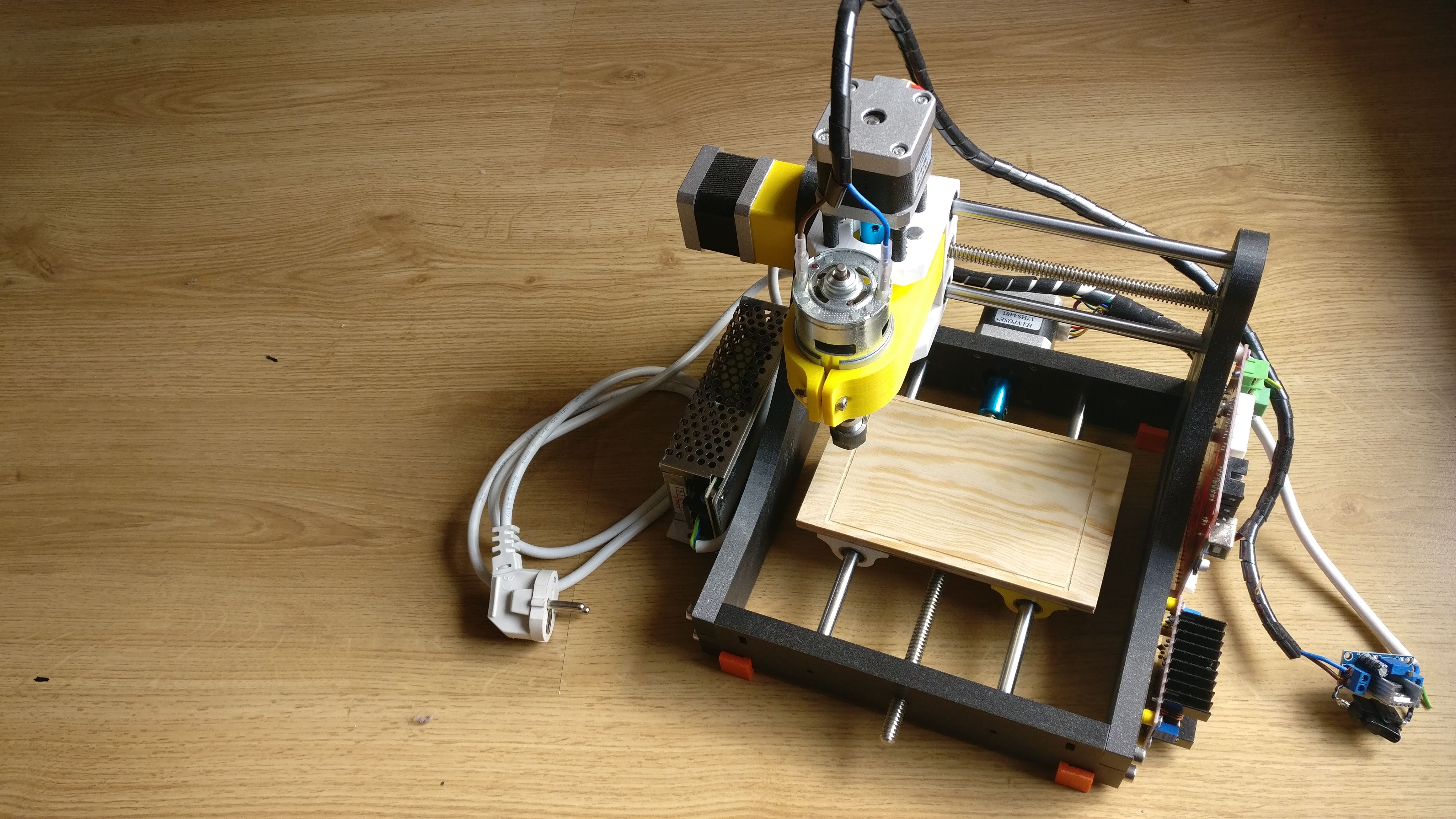
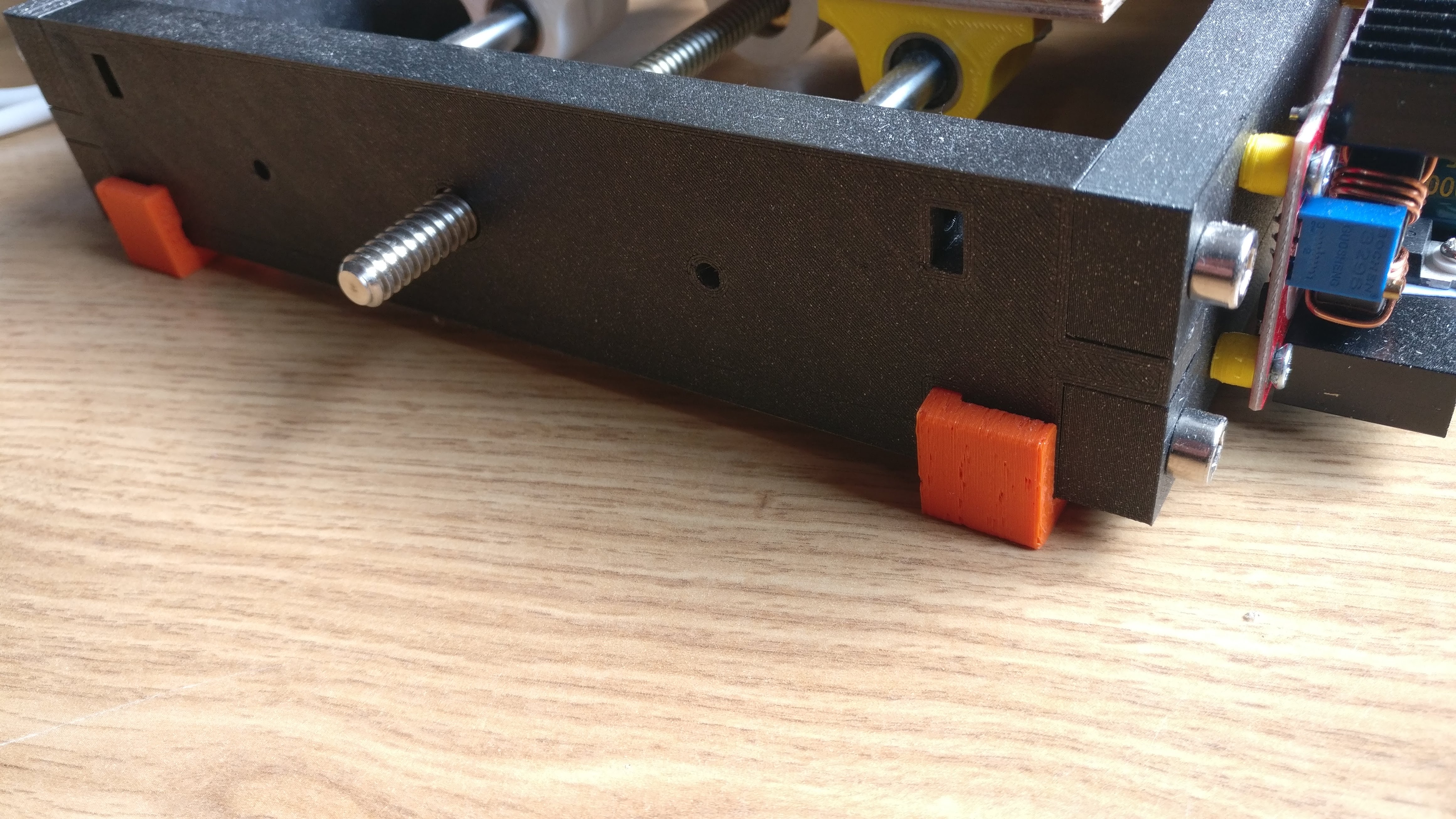
I have additionally printed rubber feets to keep it firm on the ground and some distance tubes for electronics attachment.
What’s next
Putting everything together was not the final step. I had to make it work. In next posts I will describe what firmware I have used and how I have changed it, issues with driving sindle and results of first engravings.